
Larix A
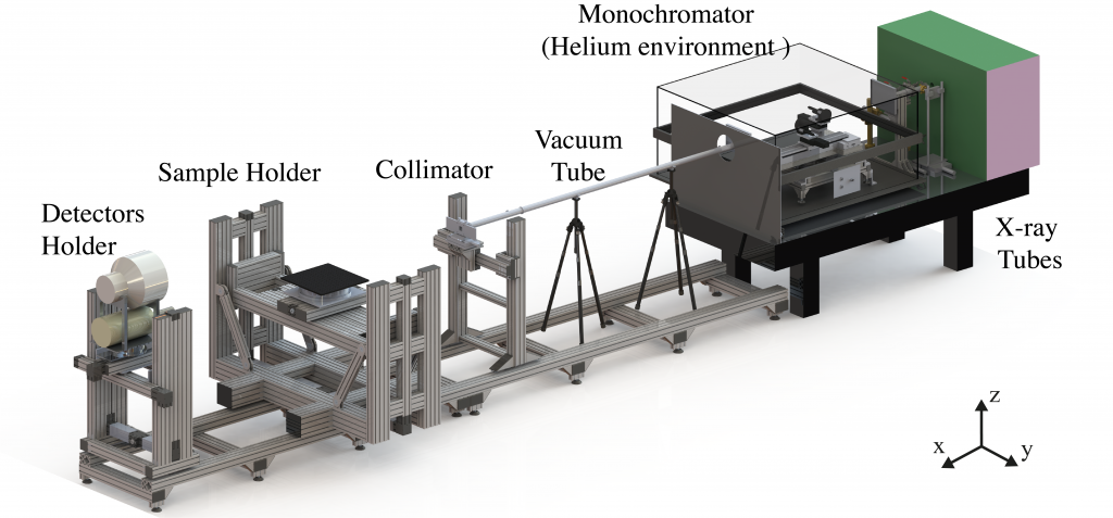
LARIX A is a 12 m beamline equipped with an x-ray tube, providing a total power of 1.8 kW with voltages up to 225 kV, and a Bragg-Bragg fixed exit monochromator, providing a monochromatic beam from 10 up to 200 keV. Thanks to the facility flexibility is ideal for performing linearity tests of hard X-ray detectors, for reflectivity measurements of X-ray reflector samples and to perform ground calibration of hard X-ray experiments.
LARIX-A Overview
The facility is equiped with the following instrumentation:
– Source: Bosello x-ray tube; 9 – 225 keV; max. Power 1.8 kW
– Bragg-Bragg fixed exit monochromator
– Adjustable collimator near the sample for a beamsize from 0.1 mm x 0.1 mm to 1.0 mm x 1.0 mm
– X-ray beam path environment: vacuum system and helium
– Sample Holder: 3 linear axis and 1 rotation
– Spectrometer ORTEC nitrogen-cooled HPGe
– Imager Thales 1024 x 1024 px; 0.3 mm pitch
– Sample environment: Clean room class 105 and thermal control system with a stability of ±2°
– Console room for the remote ajdustment of the instrumentation.
The control room is separated from LARIX A by means of a wall 2.1 m high, made of Al+Pb. From the control room, it is possible to operate all the instrumentation of the beamline, while several BNC, RS-232, USB and Ethernet cables of different lengths are also available for the instrumentation of the users. Four meters of the total beamline are contained inside a class 105 clean room where the sample holder and detectors are located. The clean room has a surface area of 12 m2 and a height of 2.1 m. The room is equipped with a thermal control system with a stability of ±2°. The laboratory is equipped with an UPS system where all the LARIX-A systems are connected. Several power outlets connected to it are also available for the users’ instrumentation. An overhead travelling crane (1000 kg weight–bearing, 20 m long) is installed parallel to the rails and can be used to place the instruments on the beamline.
Equipment
X-ray Generator
The X-ray tube available at the facility is produced by Bosello and is mounted onto an optical table located inside a well shielded (35 mm thick Lead) environment. The tube is equipped with a Tungsten anode and operates from 20 to 225 kV. It has two possible focal spot modes: a fine mode, with a focal spot of 0.4 mm diameter, and a broad mode, with focal spot of 1 mm diameter. The maximum power in the fine mode is 800 W, with current ranging from 0.2 to 10 mA, while in the broad mode the maximum power is 1800 W, with current from 0.2 to 20 mA. The output window is equivalent to a 0.8 mm thick Beryllium foil and fixes the low-energy threshold of the X-ray at 9 keV. By means of remotely controlled manipulators, the X-ray tube can be moved in the vertical and horizontal directions, perpendicular to the X–ray beam. The minimum step size is 8μm for horizontal translations, 24μm for vertical motions.
Monochromator
The LARIX-A facility employs a monochromator in Bragg-Bragg configuration. This configuration involves the placement of two crystals in parallel on a rotating table centered at a fixed point. Each crystal gives a symmetric Bragg reflection: the first crystal has the role of selecting the desired wavelength from the incident polychromatic beam; while the second crystal re-directs the monochromatic radiation along a direction parallel to the incident beam. This results in a fixed-exit beam independently of the photon energy selected. The crystals used are made of Si(111), size 80 x 40 x 2 mm, and with a mosaic structure (30’’ spread) in order to get a significant intensity of the monochromatic line. The monochromator uses a total of 8 PI motorized stages to monochromatize the desired energy. A software, designed in Labview, does all the required movements by just selecting the energy.
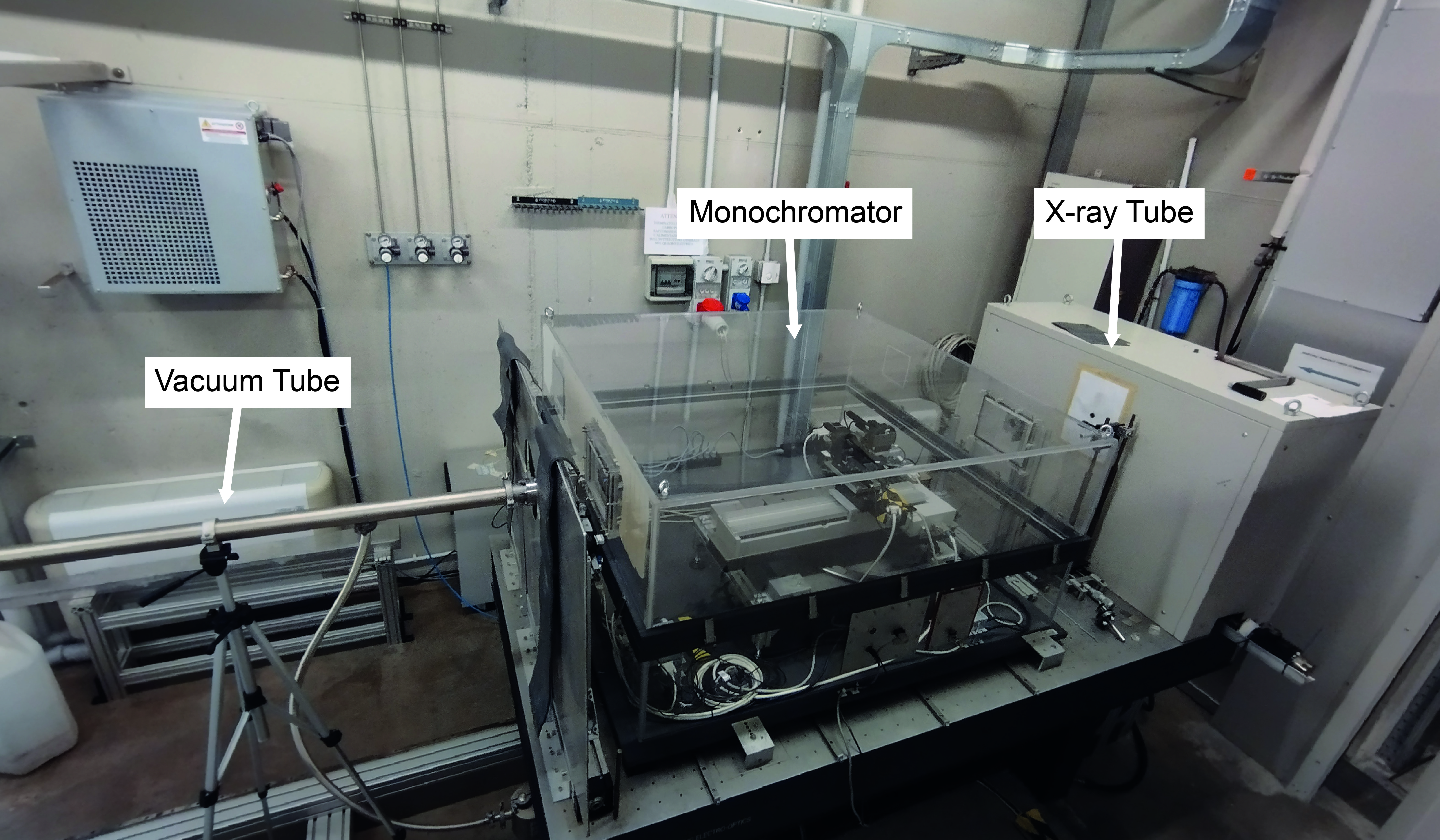
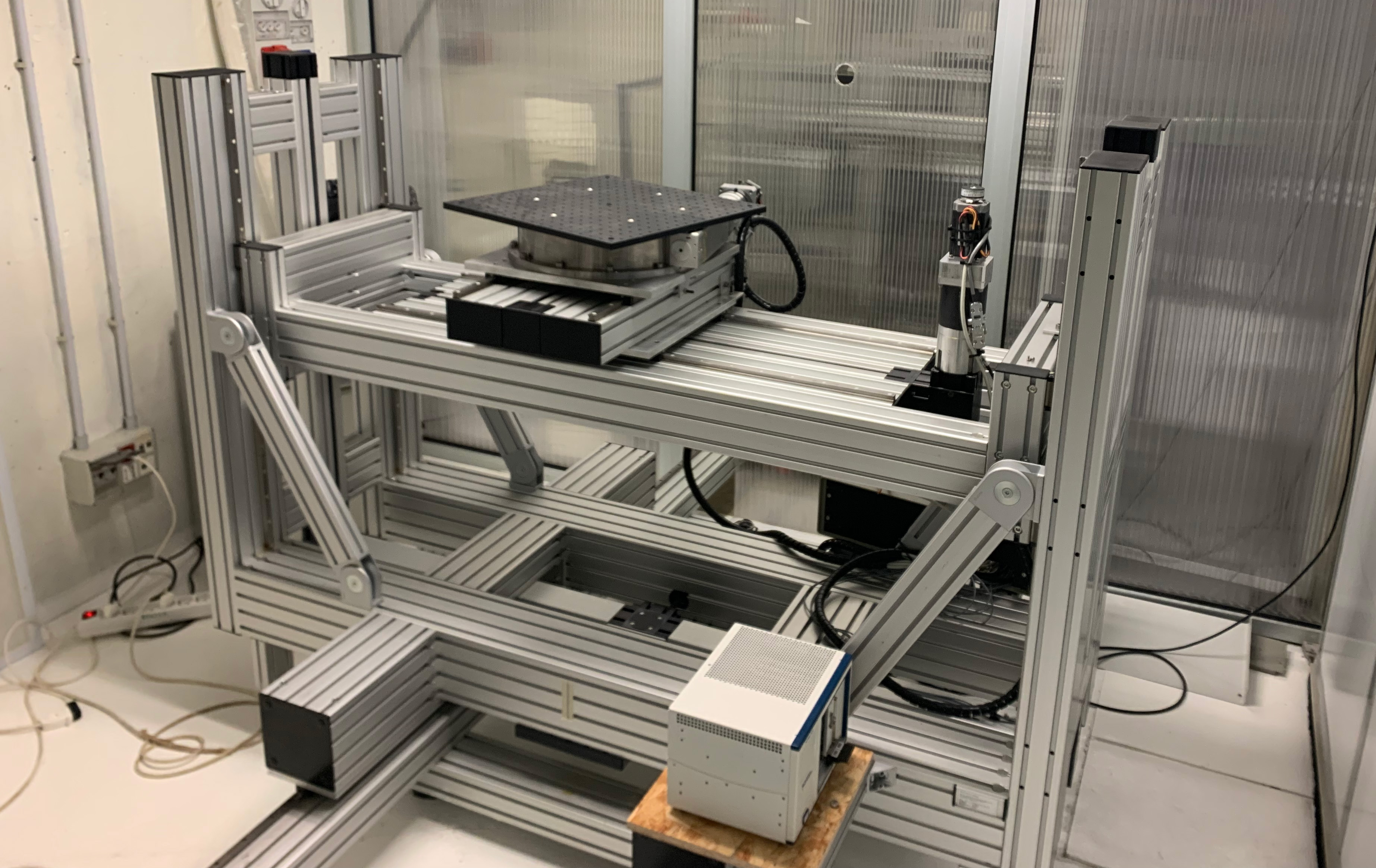
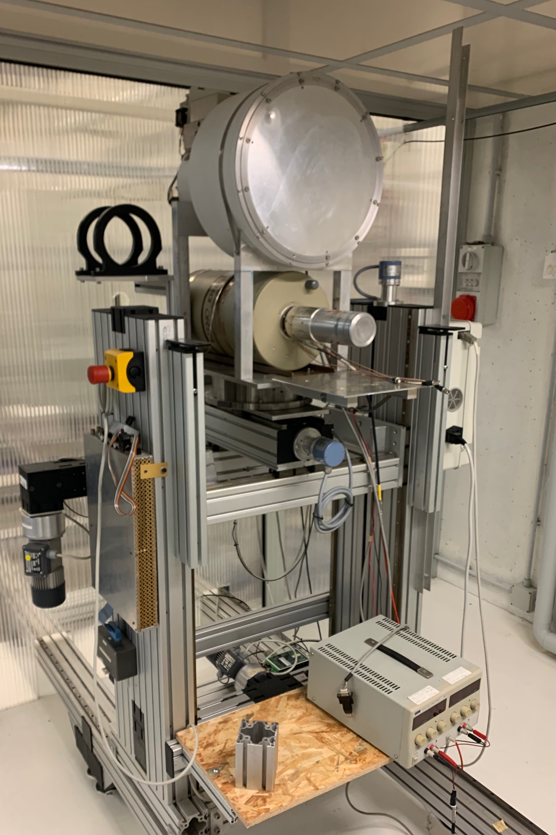
Left: Picture of the LARIX-A Monochromator system. Right: Picture showing the overall instalation of the room 1 of the facility.
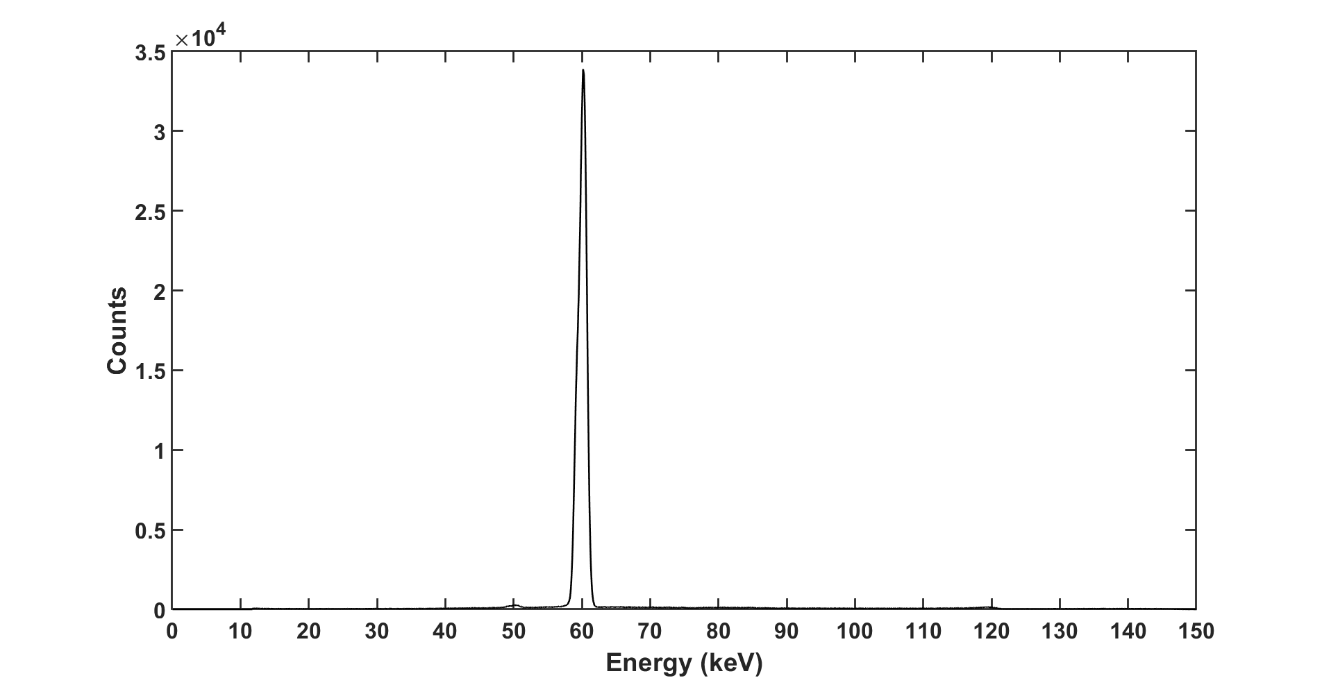
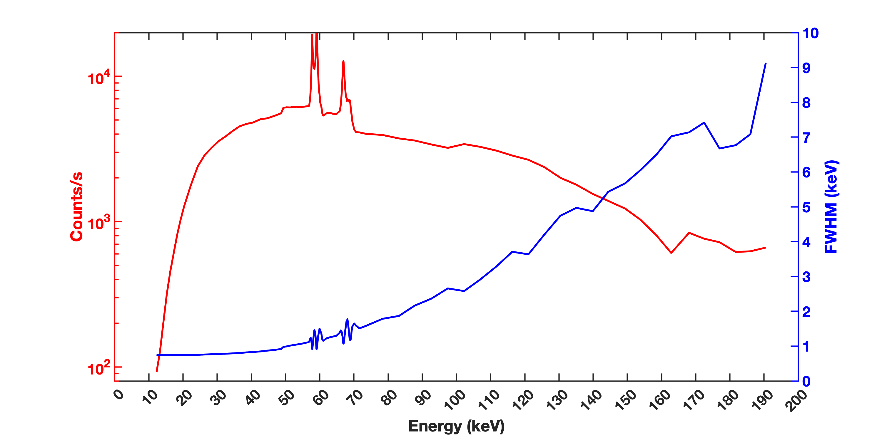
Left: Spectrum of the monochromatic x-ray beam at 61.2 keV detected with the HPGe detector. Right: Flux (red axis) and energy FWHM (blue axis) as function of the energy of the LARIX-A monochromatic beam.
X-ray beam path environment
To decrease the x-ray absorption due to the air along the path we adopted a hybrid solution using helium and vacuum. The monochromator is placed inside the vacuum tight box made of Plexiglass with size 1.3 x 1.4 m. Inside, the air is replaced by helium to get a 1 atm helium environment. Helium is the best choice due to its very high transparency at low energy (few keV). The remaining path of the beam is under vacuum. One cylindrical aluminium tube with 40 mm diameter is placed between the monochromator and sample holder inside the clean room. The length of the tube can be adjustable by coupling tubes of different sizes available in the lab. The vacuum pump available allows to get ~10-4 mbar inside the tubes. The entrance and exit windows of the tubes and plexiglass box are 0.075 mm polyethylene terephthalate (PET).
Collimators
A set of three collimators limits the divergence and the size of the X–ray beam. The first collimator is placed in front of the X-ray source in a fixed position and its opening can be manually adjusted from a minimum of 0.1 x 0.1 mm2 to a maximum of 20 x 20 mm2. The second collimator, with the same minimum and maximum opening size, is placed after the monochromator. The third one is placed just before the sample to have an adjustable and parallel beam incident on the sample. It can be manually adjusted from 0.1 x 0.1 mm2 to 20 x 20 mm2 using precision feeler gauges.
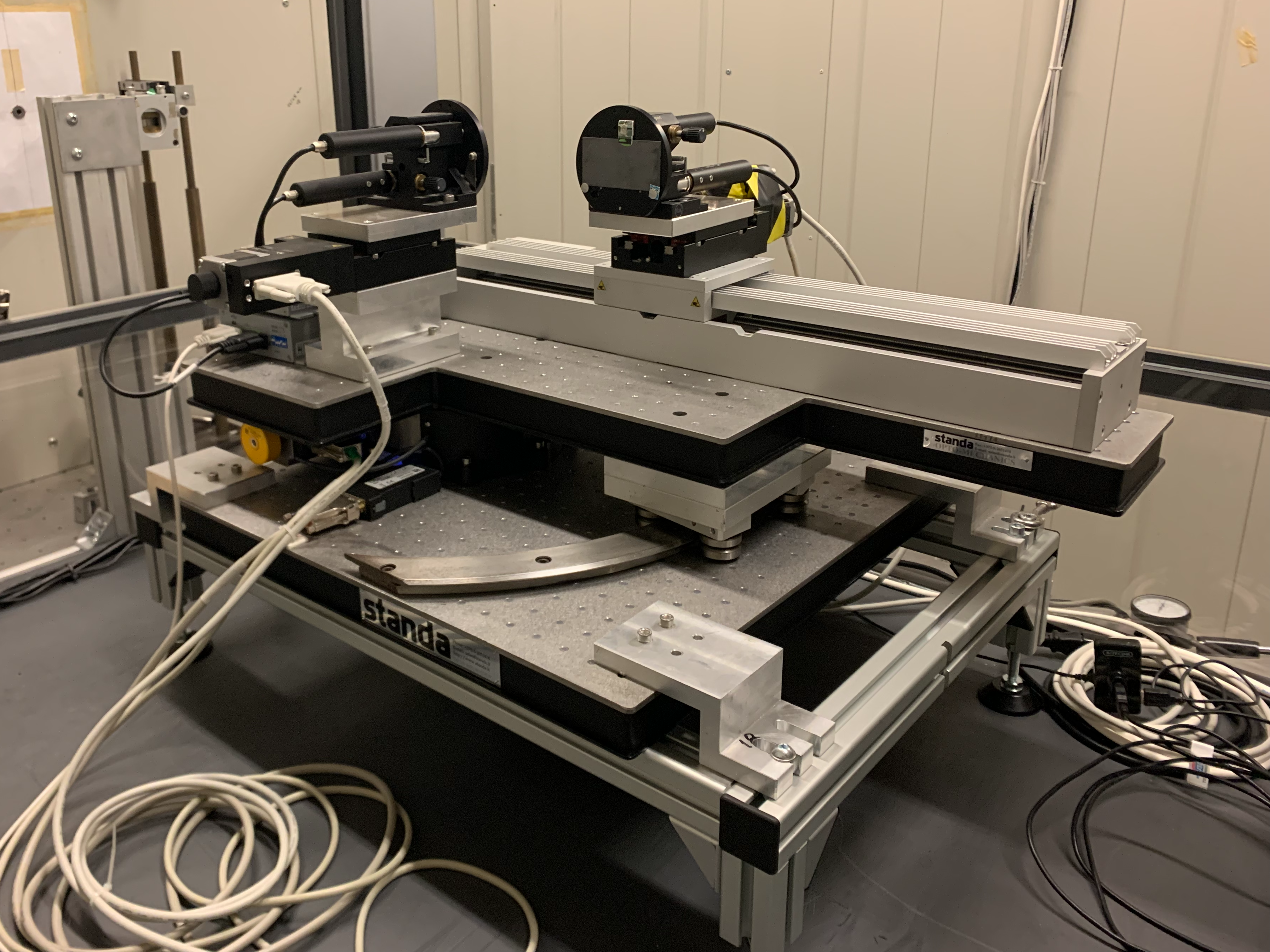
Sample Holder
The sample or detector to be tested is positioned on an optical table equipped with 4 motors allowing it to move it in three perpendicular directions (X,Y,Z) and rotate it around the vertical axis (z axis). An angular position accuracy of 3” can be achieved with a repeatability of 1”. The travel range for the y and z axis is 70 cm and 20 cm for the x axis. The sample carriage can also move manually along the rail (x axis). A standard 45 x 45 cm2 optical table with 25 mm spaced holes (metric standard) is attached on the top of the sampler holder to fix the samples. A software made in LabView allows the user to control all the 4 motors.
Detectors
Two detectors are available at LARIX-A: an ORTEC Nitrogen-cooled HPGe spectrometer, with a Beryllium entrance window; and a THALES X-ray imager detector made of CsI scintillators coupled with a CCD camera, granting a very fine (300 microns) pixel pitch. The detectors can be remotely translated in the yz plane and manualy translated along the x axis. Their main characteristics are:
ORTEC HPGe Spectrometer:
– Detector Diameter: 25 mm
– Detector Thickness: 13 mm
– Beryllium Window Thickness: 0.254 mm
– Energy Resolution: 300 eV @ 5.9 keV; 545 eV @ 122 keV
Thales imager detector
– Detector Diameter: 30 cm
– Pixel Pitch: 0.3 mm
– Pixel Number: 1024 x 1024
– Maximum Integration Time: 2 s
– Detection Efficiency: 79% @ 60 keV; 32% @ 100keV
Picture of the Detectors holder carriage with the imager on top and spectrometer on bottom.